

Battery-powered applications have become commonplace over the last decade, and such devices require a certain level of protection to ensure safe usage. The battery management system (BMS) monitors the battery and possible fault conditions, preventing the battery from situations in which it can degrade, fade in capacity, or even potentially harm the user or surrounding environment. It is also the responsibility of the BMS to provide an accurate state-of-charge (SOC) and state-of-health (SOH) estimate to ensure an informative and safe user experience over the lifetime of the battery. Designing a proper BMS is critical not only from a safety point of view, but also for customer satisfaction.
The main structure of a complete BMS for low or medium voltages is commonly made up of three ICs: an analog front-end (AFE), a microcontroller (MCU), and a fuel gauge (see Figure 1). The fuel gauge can be a standalone IC, or it can be embedded in the MCU. The MCU is the central element of the BMS, taking information from both the AFE and fuel gauge and interfacing with the rest of the system.
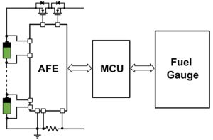
Figure 1: BMS Architecture
The AFE provides the MCU and fuel gauge with voltage, temperature, and current readings from the battery. Since the AFE is physically closest to the battery, it is recommended that the AFE also controls the circuit breakers, which disconnect the battery from the rest of the system if any faults are triggered.
The fuel gauge IC takes the readings from the AFE, then uses complex cell modeling and advanced algorithms to estimate key parameters, such as the state-of-charge (SOC) and state-of-health (SOH). Similar to the AFE, some of the fuel gauge’s tasks can be included in the MCU code; however, using a dedicated fuel gauge IC, such as MPS’s MPF4279x fuel gauge family, offers several advantages:
- Efficient design: Using dedicated ICs to run complex fuel gauge algorithms allows designers to use MCUs with lower specifications, reducing overall cost and current consumption.
- Improved insights and safety: A dedicated fuel gauge can measure the individual SOC and SOH of each series cell combination in the battery pack, which enables more precise measurement accuracy and aging detection over the lifespan of the battery. This is important because cell impedances and capacities can diverge over time, leading to run-time and safety implications.
- Fast time-to-market: Fuel gauge ICs come fully tested for a variety of situations and test cases. This reduces the time and cost of testing complex algorithms, while simultaneously enabling faster time-to-market.
Improving State-of-Charge (SOC) and State-of-Health (SOH) Accuracy
The main goal when designing an accurate BMS is to deliver a precise calculation for the battery pack’s SOC (remaining runtime/range) and SOH (lifespan and condition). BMS designers may think the only way to achieve this is to use a very expensive AFE with precise cell voltage measurement tolerance, but this is just one factor in the overall calculation accuracy. The most important factors are the fuel gauge cell model and fuel gauge algorithm, followed by the ability of the AFE to deliver a synchronous voltage-current reading for the cell resistance calculation.
The fuel gauge uses its internal algorithm to run complex calculations that convert the voltage, current, and temperature measurements into SOC and SOH outputs by analyzing the relationship of these values with the specific cell model stored in its memory. The cell model is generated by characterizing the cell across different temperature, capacity, and loading conditions to mathematically define its open-circuit voltage, as well as resistive and capacitive components. This model enables the fuel gauge’s algorithm to calculate an optimal SOC based on how these parameters change across different operating conditions. Therefore, if the fuel gauge’s cell model or algorithm are not accurate, the resulting calculation is not accurate, no matter how precisely the AFE’s take measurements. In other words, implementing a highly accurate fuel gauge has the largest effect on the BMS’s SOC accuracy.
Voltage-Current Synchronous Reading
Although almost all AFEs provide different ADCs for voltages and currents, though not all of them provide actual synchronous current and voltage measurements for each cell. This feature, called voltage-current synchronous reading, enables the fuel gauge to accurately estimate the cell’s equivalent series resistance (ESR). Since the ESR changes across different operating conditions and over time, estimating the ESR in real time allows for more accurate SOC estimates.
Figure 2 shows how the SOC error with synchronous reading is significantly lower than the error without synchronous reading, especially after a few discharge cycles. These results were extracted using the MPF42791, which integrates ESR detection and thermal modeling.
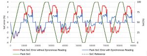
Figure 2: SOC Error Comparison with and without Synchronous Reading
AFE Direct Fault Control
As mentioned previously, the most important role the AFE plays in the BMS is protection management. The AFE can directly control the protection circuitry, protecting the system and the battery when a fault is detected. Some systems implement the fault controls in the MCU, but this results in a longer response time and requires more resources from the MCU, increasing firmware complexity.
Advanced AFEs use their ADC readings and user configurations to detect any fault conditions. The AFE reacts to faults by opening the protection MOSFETs to ensure true hardware protection. AFEs are also fully tested, which makes it simple to guarantee a robust safety system. In this way, the MCU can be used as a secondary protection mechanism for a higher level of safety and robustness.
The MP279x family integrates both forms of protection control. This allows designers to select whether the fault responses and/or protections are controlled through the AFE or MCU.
High-Side vs. Low-Side Battery Protections
When designing a BMS, it is important to consider where the battery protection circuit-breakers are placed. Generally, these circuits are implemented with N-channel MOSFETs since they have a lower internal resistance compared to P-channel MOSFETs. These circuit-breakers can be placed either on the high side (positive terminal of the battery) or the low side (negative terminal of the battery).
High-side architectures ensure that the ground (GND) is always well referenced, which avoids potential safety and communication issues when there are short circuits. In addition, a clean, constant connection to GND helps reduce reference signal fluctuations, which is key for precise MCU operation.
However, driving the gate of the N-channel MOSFETs when they are placed in the battery’s positive terminal requires voltages higher than the battery pack voltage, which makes the design process more challenging. As a result, dedicated charge pumps integrated into the AFE are commonly used for high-side architectures, which increases the overall cost and IC current consumption.
For low-side configurations, the charge pump is not necessary since the protection MOSFETs are placed at the battery’s negative pole. However, it is more difficult to implement effective communication in low-side configurations because there is no GND reference when the protections are open.
The MP279x family uses a high-side architecture which provides robust protection while minimizing the BOM. In addition, high-precision charge pump control allows for an N-channel MOSFET soft turn-on function, which does not require any additional pre-charge circuitry, further minimizing BOM size and cost. Soft turn-on is achieved by slowly increasing the protection FET’s gate voltage, allowing a small current to flow through the protections to pre-charge the load (see Figure 3). Several parameters can be configured to ensure a safe transition, such as the maximum allowed current, or the time until the protection FETs are closed without triggering a fault.
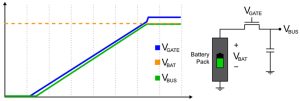
Figure 3: Soft Turn-On Scheme for the MP279x Family
Cell-Balancing to Extend Battery Life
Battery packs that power larger systems (e.g. e-bikes or energy storage) are made up of many cells in series and parallel. Each cell is theoretically the same, but due to manufacturing tolerances and chemical differences, each cell often has slightly different behavior. Over time, these discrepancies become more significant due to different operating conditions and aging, severely impacting the battery performance by limiting its usable capacity or potentially damaging the cells. To avoid these hazardous situations, it’s important to periodically equalize the cell voltages in series via a process called cell balancing.
Passive balancing is the most common way to equalize cell voltages, and it requires discharging the most charged cells until they all have equal charge. Passive cell-balancing in AFEs such as the MP279x family can be accomplished externally or internally. External balancing allows for larger balancing currents, but also increases the BOM (see Figure 4).
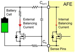
Figure 4: External Cell-Balancing
On the other hand, internal balancing does not increase the BOM but it generally limits the balancing current to a lower value due to heat dissipation (see Figure 5). Consider the cost of the external hardware and the target balancing current when deciding between internal and external balancing.
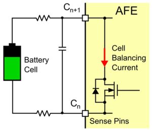
Figure 5: Internal Cell-Balancing
Another important aspect of cell-balancing is the physical connections. For example, the MP279x AFE family uses the same pins for both voltage sensing and balancing. This significantly reduces the IC size, but means that consecutive cells cannot be balanced simultaneously, increasing the time it takes to perform the cell balancing. Using dedicated balancing pins reduces the balancing time, but significantly increases the IC size and overall cost.
AFE Safety Functions
As explained throughout this article, the AFE controlling the system’s protections and fault responses is extremely important in BMS designs. Prior to opening or closing the protection FETs, the AFE must be able to detect these undesirable conditions.
Cell- and pack-level faults, such as over-voltage (OV), under-voltage (UV), over-current (OC), short-circuit (SC), over-temperature (OT), and under-temperature (UT) faults should all be monitored. However, there are other beneficial protections and functionalities that AFEs can offer for certain applications. For example, self-testing allows the IC to detect whether its internal ADC is malfunctioning, which prevents the system from incorrect measurements. Enhanced watchdog timer functionalities also ensure robustness and security when the main MCU is not responding.
The MP279x family provides the faults protections listed above with a high degree of configurability, enabling the user to define different thresholds, deglitch times, and hysteresis for each fault. These devices also rely on two different comparators for SC and OC fault conditions to minimize the response time. They offer configurations for fault auto-recovery as well, meaning that they can automatically recover from most faults without requiring any action from the MCU.
Conclusion
The BMS monitors the battery pack to protect both the battery and the rest of the system. A substandard BMS not only reduces the system’s safety, but it also provides inaccurate battery SOC management. These inaccuracies have a very significant effect on the product’s final quality, as they can result in potentially dangerous faults, or faults that negatively impact user experience. To mitigate these issues, this article explained what designers should expect and look for when designing their BMS.
To learn more about how battery management systems work and how to design them, MPS offers full BMS evaluation kits. Using these tools, designers can easily test and configure their BMS through easy-to-use GUIs and extensive support materials, making it easier to tailor their devices to specific application requirements.